Summary
The solar and electrical system on the van was one of the most daunting tasks during the entire build process.
If I’m being honest
This was the project that I had the least amount of knowledge on, so it required the most amount of research. So hopefully this break down of my electrical and solar system will help you plan out yours.
One of the hardest parts of sizing your solar system is to determine just how big of a system you need to meet your daily usage. The reason it takes so much time and effort is because most people have never really had to think about their daily power consumption.
So if you want to be lazy and avoid the need for all calculations you can just copy my exact system and never have to worry about it. I run;
- Electric induction cooktop,
- Fridge / freezer combo,
- Kettle, blender,
- Lights, water pump,
- Charge a computer,
- Charger cameras,
and many other things and have never had any issues.


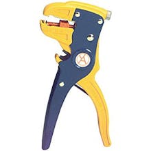
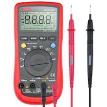
Tools used


When building out your van you will learn that the majority of the wiring in these conversions are 12v wiring. This is done for many reasons but the main reason is that the majority of 12v appliances are drastically more efficient. This garage of wire is overkill for 99% of applications in the van. I used it mainly because it’s a very durable wire that made all my connections easier to manage.
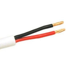
For all of the outlets in the van I just used standard 14/2 House wiring with a ground. Wire is relatively inexpensive and so are outlets so I put outlets everywhere I thought I might need one. My van has 6 outlets installed in it which allows me to easily charge any device no matter where I happen to be sitting when working in the van.
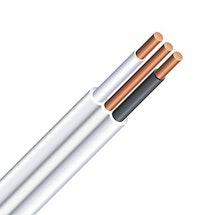
On my van I run a 110v electric hot water tank. Due to the larger power draw in comparison to all of the other AC circuits, it requires a larger gauge wire to handle the increased current is used. For my build I only needed about 10ft of this wire which I was able to purchase by the foot off a reel at Home Depot.
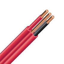
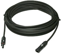
The solar panels that I ordered came with a fairly standard 10 gauge solar wire so I purchased more of the same wire that I used to run the wire from the panels into the vehicle. Lots of sites online have pre made cables with the proper connections on them. For my build I was able to locate a local solar supply store and have them cut the cables to my length and install the ends for me.
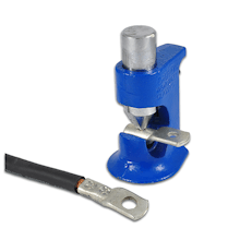
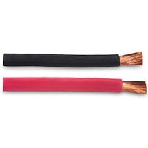
In my build I used (2) 6V AGM batteries and to connect the batteries I used 4/0 welding cable. Welding cable is much easier to work with due to its increased flexibility and can be picked up from most battery supply stores. The one thing to note is when working with welding cable is that you need to install your own cable ends with a crimping tool.
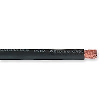
With my electrical install I wanted to have the capability to charge the house batteries off of the engine alternator. In order to accomplish this I needed to connect the house batteries to the alternator. For this wiring run I used 1/0 welding cable and ran it through an ACR to manage the charging between the starting battery and the house battery.
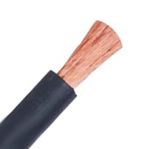
The last wire size that I used was some smaller 6 AWG welding cable. You will see below where this was used in connecting some of the 12v solar components together. I was a big fan of using the welding cable over traditional battery cable mainly due to the increased cable flexibility making it easy to fish around and make it look neat.
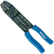
For most of the 12v wiring work, I used crimp on connectors. In my build, a combination of blade and ring style connectors were used. When you're buying these types of connectors, make sure they're matched to a range of wire sizes to ensure you get the proper connector size for the wire being used on your build.
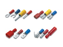
When dealing with the welding cable, you can just purchase standard sizes that already have the ends installed on them. I wanted to have the flexibility of changing the wire path and cutting the cables to the exact size needed. You'll find that you might adjust where certain components are going to be positioned. Having the ability to adjust the cable length makes this process much smoother. When using crimp on ring terminal connectors, the terminal comes specific for the wire size they're being crippled on to. Also, you need to know the lug size so the right terminal diameter is used. Making sure you get all the right sizes of connectors can be a bit of a pain to plan out but just sit down with a piece of paper and map it all out and you shouldn’t have any problems.

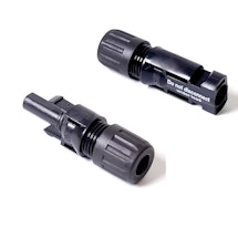
An MC4 connector is used to join the solar panels together and also to bring the solar power into the vehicle. MC4 connectors are a mechanical connection that can easily be taken apart or clicked together. Full disclosure: I have no idea how hard working these connectors are because I bought the solar wire with the ends already installed.
The final type of connector that I used in a few places on the build was marettes. I only had to use these in a few places when running the 110v wiring outlets. I don’t love using this type of connector but for my requirements it worked fine. I just made sure to tape up all of the fittings once attached to ensure they don’t fall off when I'm driving.

An ACR is an Automatic Charge Relay. This unit allows you to connect your house batteries and engine-starting battery together safely. The benefit of using this unit is that it has the ability to intelligently tell when your vehicle battery has reached maximum charge, then it will begin to send charge to the house batteries. For my system this has been a total life saver and I have barely had to worry about my available house battery power. My van has a lot of high energy consuming devices (fridge, cooktop, hot water tank) and so far it’s worked out really well.
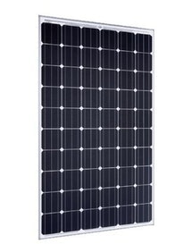
Using (2) 260W 24V Panels, I have 520W total solar power on the roof of my van. The reason for going with a 24v panel over a 12v panel is because the cost was roughly half the price for the panels and my charge controller can handle both so I opted to get the less expensive panels. Also when I designed my roof rack on the vehicle I made it so that it can also accommodate 320W panels so if I ever find myself needing to generate more power I can increase the solar array from 520W - 640W without any drastic changes to the vehicle.
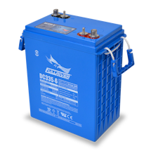
When it comes to batteries, you have a ton of different options that you can choose from. Originally I had looked at using Lead Acid batteries so I could save a little bit of money but after more research, and the potential of having harmful gases escape into the vehicle, I went with AGM Batteries. The batteries that I decided to go with were (2) 6V 335Ah AGM Batteries made by Fullriver. With AGM batteries you can safely discharge them to 70% on a regular basis and its fine to take them down to 50% every couple weeks. That means that I can safely use between 100 - 150 aH of battery, which for my power consumption has been plenty.
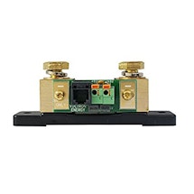
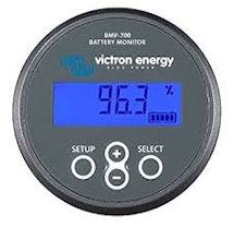
I decided to use a lot of the Victron Energy solar components on the van. The Battery Monitor that I went with is the BMV-702 from Victron Energy. In simplest terms, a BMV is like a fuel gauge for your batteries. It will tell you the voltage, current, percent of battery remaining and ampere-hours consumed. The main reason that I went with the Victron BMV is that it also comes with a Bluetooth capability that allows you to get all the information off the BMV directly onto your phone. This feature is really not necessary but for a guy like me who is attracted to all things tech it was a must-have on my build. When installing the BMW you will also need to install the 500A/50mV shunt provided in order for the BMV to function properly. Basically the shunt allows measurements to be taken across two points in the circuit. The resulting information displayed on the digital read out, without the shunt in the system the BMV, would not be able to acquire the necessary information to the user.
The Battery Monitor that I went with is the BMV-702 from Victron Energy. In simplest terms, a BMV is like a fuel gauge for your batteries. It will tell you the voltage, current, percent of battery remaining and ampere-hours consumed. The main reason that I went with the Victron BMV is that it also comes with a Bluetooth capability that allows you to get all the information off the BMV directly onto your phone. This feature is really not necessary but for a guy like me who is attracted to all things tech it was a must have on my build.
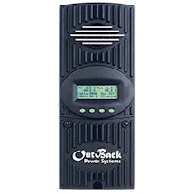
I consider the charge controller as the brain of the solar system. This unit is what manages how much charge you're going to be putting into the batteries. I went with the FM60 Charge Controller from Outback simply because... well... A friend of mine had the exact same one in his house and he was very familiar with it so he was able to help me install it as well as troubleshoot any issues I might have while on the road. The FM60 charge controller also allowed me to have an AUX load off the controller which was required to run my hot water system in the fashion I had planned.
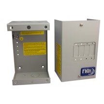
General use enclosure for retrofits, small inverter disconnect, PV disconnect, AC or DC distribution or other uses. Accommodates up to four panel mount type breakers from 5 Amps to 100 Amps. I used this box in my solar system to function as a shut off the the Charge Controller, Solar Panels and as a main disconnect on all 12v circuits in the van.
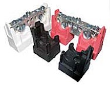
These busbars are designed to fit inside of the Midnite solar breaker box and snap in place. With all the wiring on my system, I only placed the Red Busbar inside the breaker box and the black one outside the box to leave some more room for wire in the box.
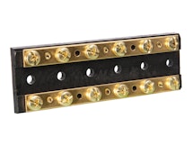
Using a busbar is very similar to using a terminal block above. The main difference is that with a terminal block your circuits are kept separate where as with a busbar everything is combined. In my system I used a busbar on both the negative and positive side to keep the wiring neat and easy to troubleshoot. Using the busbar allowed me to run a few positive wires from the 12v fuse panel to the upper control panel, connect them to a separate busbar, and wire many electrical components off of that bar.
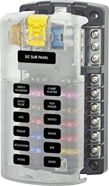
I ran power to this Blue Sea 12v fuse panel from the 12v breaker box. This panel allows for easy circuit management and to have these different circuits fused independently. By splitting up the 12v circuits you have inside the van it will make troubleshooting things in the future much easier. This particular fuse panel also had a nice negative busbar section at the top, making it easy to combine all the ground in the circuit.
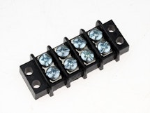
A terminal block is a really good way to keep your wiring neat and easy to follow. Since the majority of my wiring went from under the passenger bench, up to the control panel then out to the electrical device, I decided to use a terminal block in each location to terminate the wire in that area and keep the wiring as neat as possible. Electrical terminal blocks provide a convenient way to connect individual electrical wires
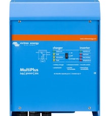
I decided to go with a Battery Based Inverter Charger for my build. An inverter’s main job is to convert DC power produced by the solar array into usable AC power. I wired as many of my electrical items with 12v power such as lights, fridge, fans, backup camera, etc. For the items that require AC power I decided to go with an Inverter Charger. The inverter charger not only produces AC power to be used in the vans standard outlets but can also be plugged into any power source and used to top up the vans house AGM batteries.
I used a 400A ANL fuse from Blue Sea to protect the system. A fuse is basically a piece of wire designed to melt and separate in the event of excessive current. A fuse is always connected in series with the components to be protected from over-current. I bought 2 fuses just so I had an extra in case anything ever happened.
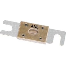
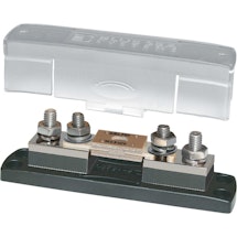
The fuse above that was purchased requires a special holder in order to properly use the fuse.
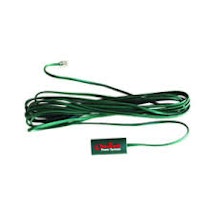
The RTS and a Remote Temperature Sensor is not something that comes with the charge controller but needs to be purchased. The RTS helps the charge controller monitor the temperature of your batteries to avoid any risk of over charge and potential damage to the batteries.
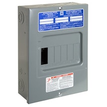
I went with this breaker box to control the 110v aspects for the wiring in the van. I used (2) 15A breakers to support the 2 outlets circuits in the van, one 20A breaker for the hot water circuit and then a double pole 60A circuit to function as the main disconnect on the whole system.
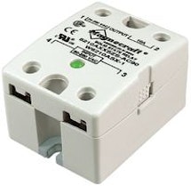
If you're familiar with my build you'll know that I used a household 110v point of use hot water heater. This type of water heater has a very hefty power draw and under normal circumstances my van wouldn’t be able to handle it, but with the auxiliary load on the charge controller and this relay I am able to take the excess power from the panels that would typically be wasted when the house batteries are full and divert that water into the hot water tank.
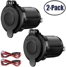
I installed a few 12v outlets to plug in the 12v fans that I purchased as well as one in the fridge sliding cabinet so I would be able to plug in the fridge and have the outlet out of sight.
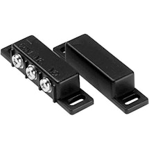
These are 100% a 'nice-to-have', but can overkill for most people. When I open and close the doors for my wardrobe and back benches, the lights go on/off automatically. It’s a nice feature for sure but definitely not required. One thing to note is that they make two types of magnetic switches, 'normally open' and 'normally closed'. For this application you want to purchase the 'normally open' switches. These switches will function so that when the two magnets are touching the circuit will be closed and the lights off… (Door closed) when the door is opened and magnets are pulled apart the lights on that circuit will turn on.
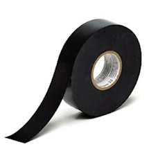
Similar to Zip Ties, using Electrical tape helps you keep all of the wiring neatly organized and stored properly. When possible, I like to use heat shrink instead of electrical tape but both have their need.
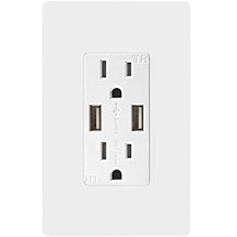
Outlets in the van are something I might have goen overboard with... I think I have 7 total. But its really handy to have outlets everywhere you need them and I upgraded to the USB outlets to help with charging all of my camera gear and electronics.
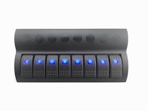
Rather than having the switches in my van scattered throughout, I wanted to centralize them in a neat and organized upper control panel. Having all the switches all in one place allows me to quickly and easily check what’s on and off, without jumping all over the place. Marine rocker style switches such as this make it very easy to install and manage them in a single panel. One thing to note about using this type of switch panel is that each switch has its own pop fuse and they vary from 5-20a ratings… so don’t put the fridge on one with a 5a rating like I did, you will just end up needing to switch it out.
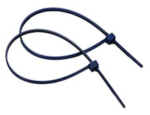
When you're doing electrical work on your van, zip ties are essential. Using zip ties helps you keep all your wiring organized. It's really easy for your wiring to become a mess. This not only makes your electrical impossible to diagnose but it can also be potential dangerous as loose hanging wires could cause a short.
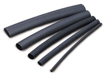
Heat Shrink is something that many people over look but if you're trying to make your work look as professional as possible, then using heat shrink helps to clean up all connections and ensure you wont have any loose connectors.
Install Process
Installing all of the electrical components certainly isn’t as straightforward as some of the other aspects of the van build. When it comes to the electrical component of the van you need to have a basic understanding of AC home wiring, DC Low voltage wiring and the solar system components.
For the purpose of this article I am not going to go into that much detail on the actual wiring of the AC and DC circuits and will focus more on the components that make up the solar system and how I have them connected together.
One thing that is very important to understand is that I am not a licensed electrician nor do I have any formal training with installing solar systems. So use all this information at your own risk.
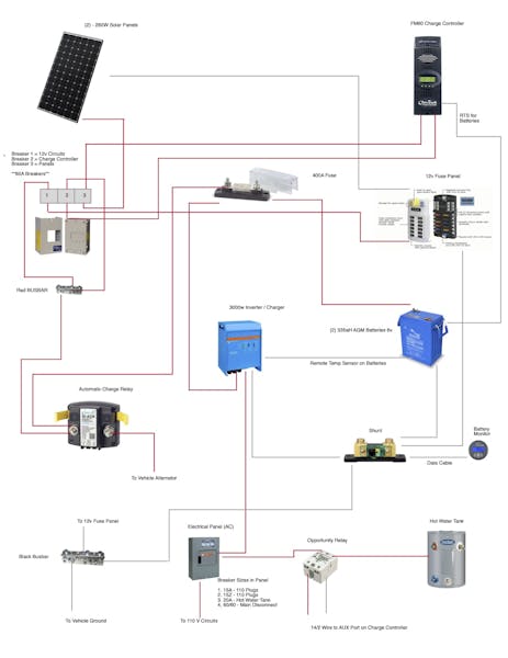
The Solar System Setup
What wire where?
For most of the connections in my system, I used a variety of welding cable and wire sizes. It takes a bit of time to map out where you’re going to place everything but once you have everything roughly in position it’s easy to see how much wire you are going to need. I know you can order all the cables pre made but I recommend buying the cable and cutting it to length yourself, then fastening all lugs on site. When using a variety of solar components you won’t always have matching cable ends as one end might be a 5/16 lug and the other a ⅜ lug. Making your own cables on site isn’t a lot of extra work, and it will make the job a lot cleaner in the end.
What wire sizes did I use?
-
4/0 Welding Cable Red and Black
Enough to get from the battery boxes to the batteries I wasn’t able to get red 4/0 so just had to use black. The 4/0 welding cable was used to connect the batteries together and the inverter to the fuse and shunt.
-
0 or 1/0 Welding Cable
For Battery 400A Fuse to ACR to DC Box Red
Connecting ACR to engine battery = Red
For General Ground to the Busbar then to the Shunt and the Busbar to vehicle ground. (Black Wire)
-
6/3 Wire AC (White Jacket)
5ft of it to connect the inverter to the breaker panel for the 110
-
6 Gauge Welding Cable Red/Black
Since I was only able to get black, I used a combination of black and some red wire from the 6/3 cable above. This was used to connect the charge controller, 12v Fuse Panel (main) and panels into the breaker box.
I used welding cable because it’s very flexible and easy to work with. If welding cable is hard to locate try phoning some welding supply shops or you can substitute for machine tooling wire.
Let’s start at the solar panels… because I need to pick somewhere to start.
Let’s Begin

For my panels I used (2) 260W Solar Panels from HESPV giving me a total of 560W. My panels are mounted on the custom roof rack and due to the size of these selected panels I do have the ability if needed to upgrade to (2) 330W panels increasing the total solar power from 520 – 660W = 140W. So far the current panel size has been adequate and getting a larger panel has not been necessary.

Once the panels are mounted, take one end of each panel and connect them together and then take the remaining 2 ends and connect them to the additional solar wire you purchased and run that inside the vehicle.

The area around this Cable Clam started to rust and it was driving me crazy…. So I had the roof sprayed to solve that problem.

To pass the wires into the vehicle I used the Blue Sea Cable Clam, these are typically used in marine applications but they seem to work great for waterproofing the area where you need to bring wires inside the van. For my van I used three of them, the first for the solar wires, the second for the router antenna wiring and the third for the rack lighting.
When installing these on the roof I suggest putting them as far back as you can on the sprinter van in the cavity above the rear doors. By putting the cable clam here you end up with a nice area inside the van to hide and fish the wires into whatever cabinet you are hoping to run them.

Once the solar wires are inside the vehicle the real fun begins… The negative wire on the solar panels I terminated it on the 12v Blue Sea Fuse Panel.

The second positive wire from the panels I brought into the Midnite solar breaker panel. Inside the breaker panel I have a single positive bus bar mounted inside as seen here

with 3 60A breakers the 3 breakers control
- All 12v circuits
- Charge Controller
- Solar Panels
In position 1 of the breaker panel the top wire goes to the red busbar inside the box and same with the top side of the position 2 breaker.
On the bottom side of position 1 I ran that wire to the positive of the 12v BlueSea fuse Panel


In position 2 the bottom wire was ran to the charge controller to act as a main shut off for that solar charge controller.
In position 3 the top of the breaker is running to the charge controller and the bottom is the positive side of the solar wire and this allows me to shut off the panels completely if I need to perform any work on the panels, as you never want to disconnect the panels on the roof while they are under load.
The Red Busbar inside of the breaker box has 3 positions I used up two of the positions described above and was able to use the third position for the ACR.

If you don’t remember from above, the ACR is an Automatic Charge Relay that allows me to charge the house batteries from the alternator once the vehicle starting battery is fully charged.
The ACR has three wires coming off it and they are all done using 1/0 welding cable. One wire runs from the Midnite Breaker box bus bar to the ACR, the second wire is the wire that connects the ACR to the vehicle battery / alternator and the third wire is connected to the 400A fuse between the (2) AGM batteries.

Ok lets move over to the batteries. I have (2) AGM batteries that are connected in series which gives my 12v 335aH Battery Bank. To connect the batteries together I used 4/0 welding cable. Then the remaining Red or positive side of the battery was connected to the 400A Fuse.


Leaving the Black or negative 4/0 cable from the batteries to be connected to the shunt.

The shunt is needed in the system if you are wanting to run a battery monitor. For my van I used the Victron Energy BMV 702 which gives me readouts on battery capacity, time left on current charge, aH drawn from battery bank etc…. So it’s really nice to have.
I’m not 100% certain on how they work exactly but I do know the 500A shunt which is included in the BMV kit measures the electricity coming across the negative and uses some magic to display these numbers.
Basically the shunt is a breakpoint in the circuit and it has the ability to pull information as the electricity passes over it. On the shunt you will also need to install a small power wire which I just ran to the 12v BlueSea Fuse Panel and then the Data cable provided plugs into the shunt and the other end to the back of the BMV display.


When you purchase the BMV from Victron you can purchase a secondary bluetooth dongle and this allows you to get the system output numbers directly to an app on your smartphone.


Moving onto the batteries
In the battery photos you will see 2 other small gauge wires, both of these wires are remote temperature sensors. The green one you see stuck to the battery is for the charge controller and then the thin wire you see on the top left negative post is for the inverter. Both of these RTS are just wire directly into the respective device and it’s clearly labelled where they plug in.

Next i’ll go over the wiring for the charge controller, basically we have 2 wires coming from the Midnite solar box these are 6awg welding cable one for the power to the charge controller and the other for the solar panels…. O yeah we also run a wire to ground the charge controller and that wire goes from the charge controller to the 12v Blue Sea Fuse Panel.
You will also notice the green wire for the RTS we talked about above and then I used some of the 14/2 in wall speaker wire to connect the bottom of the hot water relay to the AUX port of the charge controller. The charge controller is pretty straightforward to get everything wired up but will take some reading to ensure you program the controller properly to manage your batteries.

Mentioned above we talked about the large 400A fuse between the ACR and the batteries, I also ran a 4/0 welding cable wire from the same side as the ACR to bring power to the inverter.
Then from the Inverter I used 6/3 ac wire to bring power into the Breaker Box I’m using for the 110V Circuits. The 6/3 wire is awful to work with especially when it’s -20c outside so try and get the wire warm before installing and it will make it easier to maneuver this beast of a wire.
The breaker box has (2) 15A Circuits for the 110 Outlets (1) 20A Breaker for the Hot water Tank and then a Double 60A which is functioning as the main disconnect on the system since Im using a sub panel I had to hack the system this way to get a main disconnect.


The regular 110v wiring is fairly straight foward and I’m not going to go into much detail on that here. Just youtube how to wire an outlet and you will get a few thousand results. In fact i’ll take care of that for you just click here and watch one.
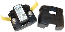
Hot Water Relay
One thing I do want to touch on quickly is this little relay I used for my hot water tank
This little relay as you can see the bottom connects to the charge controller aux port and the top is placed inline with the positive wire going to the hot water heater. It’s a fairly simple install but what it does is allows you to almost trickle charge your water once the house batteries are full.
For those of you who are familiar with solar charging the charge controller will take your batteries through a few stages depending on the current voltage of the batteries.
In the morning your system will be in bulk mode and this means all available solar power will be sent to the batteries to charge them back up.
Once your batteries reach a nearly full charge which for my batteries total charge is 14.8 so my nearly full is around 14.2, the charge controller will then begin its absorb stage. The absorb stage of the charging cycle is a timed period for me 1.5 hours where the batteries will consume all the power they can at the highest voltage possible.
During this stage the relay will start to pulse a bit and send small amounts of energy into the hot water circuit. After the 1.5 hours of absorbing is complete then voltage will drop and you will enter a float stage. During float is when the relay will allow the most amount of electricity into the hot water tank as the charge controller at this point is only trying to maintain the battery level and not charge it anymore.
Hopefully that makes sense for the charging cycles and how the relay for my hot water tank works. Also keep in mind you can override the relay inside the charge controller and turn it to always on when driving and create your hot water that way as well. Also all of the voltage settings and absorb times will vary depending on the batteries you use in your system, final thing to note on this is what not every day will you hit the float or absorb stages which is fine it just means you won’t be making hot water that day unless going for a drive.
The last item on the system is the negative busbar which ties the house system ground the vehicle grounds all together.


On the left that wire goes to the vehicle to tie the grounds together


The middle wire is coming from the 12v Fuse Panel bringing all those together and the far right is heading to the shunt tying the negative side of the batteries to the rest of the system.
Cabinets Circuits
So the above outlines the main components of the solar and electrical system in the van. Once you have a decent understanding of how that all works getting all the 12v circuits hooked up is fairly easy.
From all of the circuits in the 12v system are going to get their power from the 12v Blue Sea Fuse Panel.
From this I ran the various wires up to the control panel as that is where I wanted the switches for the system to be located. When you look at my cabinet set up it probably looks intimidating but it’s really straightforward.
One thing to notice is that you don’t need to run a seperate wire from the Fuse Panel the cabinet for each and every device in the van. You can combine certain devices into the same circuits and still have them independently switched. In my van I believe I ran 3 wires so I could separate all my items into three circuits and then 3 additional wires for the tank meter system as each tank (grey, black and fresh) requires a pair.
Originally I had thought I ran more than enough wires into the cabinet but with the tank sensors it didn’t take long use them all up.

When wiring in all the components for the van if you’re going to use a central control station such as I did you are going to all the wires that you plan to have on the switch panel in the cabinet to be fed back to that cabinet.


Lower section where the bench will eventually be installed.


Above you can see all the wires coming in the bottom of the box from the passenger side bench and then the top wires are the wires coming in from the different devices.
Pro Tips
Magnetic Switches
On my van build I used some magnetic switches to trigger the wardrobe doors and side benches LED lights when opened. To most people it probably seems un necessary and…. You are right, but it was really cheap to buy the switches and I had lots of leftover LED light strips. So if you have the time I suggest doing it because it makes digging around in your closet in the middle of the night much much easier.

Marine Rocker Switch have a fuse
In my control panel area that I located all my switches you will see that I used 8 panel marine rocker switch. One thing to note is that each switch if you remove the white faceplate has its own built in fuse ranging from 5-15 A. So just keep this in mind as I originally had my fridge on a 5A switch and it popped the fuse on me before I knew about those fuses…. Lets just say i wasted a good couple hours troubleshooting a 10 second fix.
Make your own cables
I know online there are lots of websites that you can buy pre made cables for your solar system. After going through this I highly recommend buying lengths of cable and ends and building your own cables. The downside of making your own cables is that you need to purchase a tool for putting the lugs on the cable ends and crimping them properly, but I found that doing things this way made for a much cleaner install and I was never short of cable or trying to figure out how to use up additional unnecessary wire in the small cabinets.

Gallery
VIEW ALL


Author
Scott Adamson
Vanlife aficionado with his rescue dog Ellie. We travel around North America in search of good times and fresh coffee.